
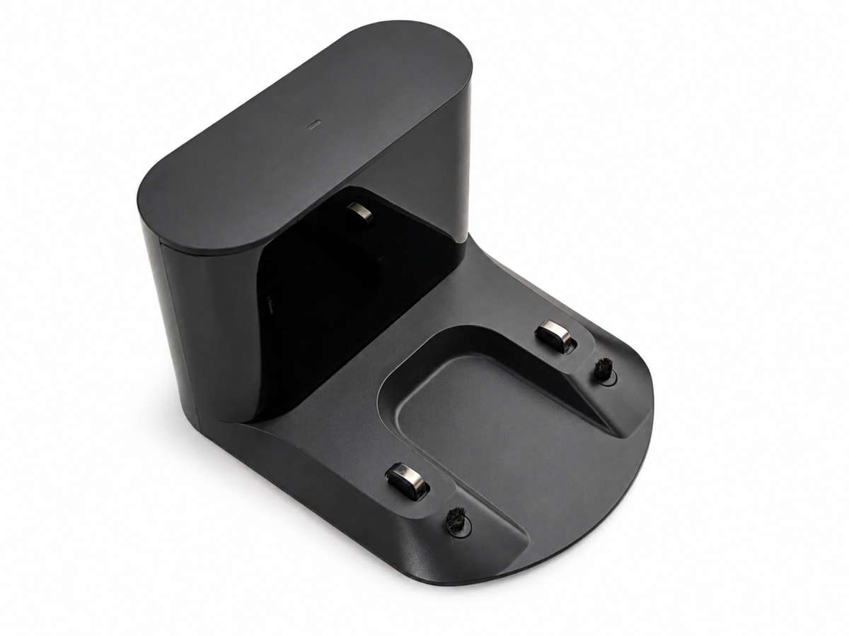
I had a defective original Roborock charging dock lying around, compatible with models including the S5, S6, S7, Q7 and S8. The dock appeared completely dead: there was 0 V at the charging contacts.
Since I had already bought a replacement dock, this was a good opportunity to open the old one and systematically find out what had failed.
Opening the charging dock
Opening the CDZ12RR is straightforward.
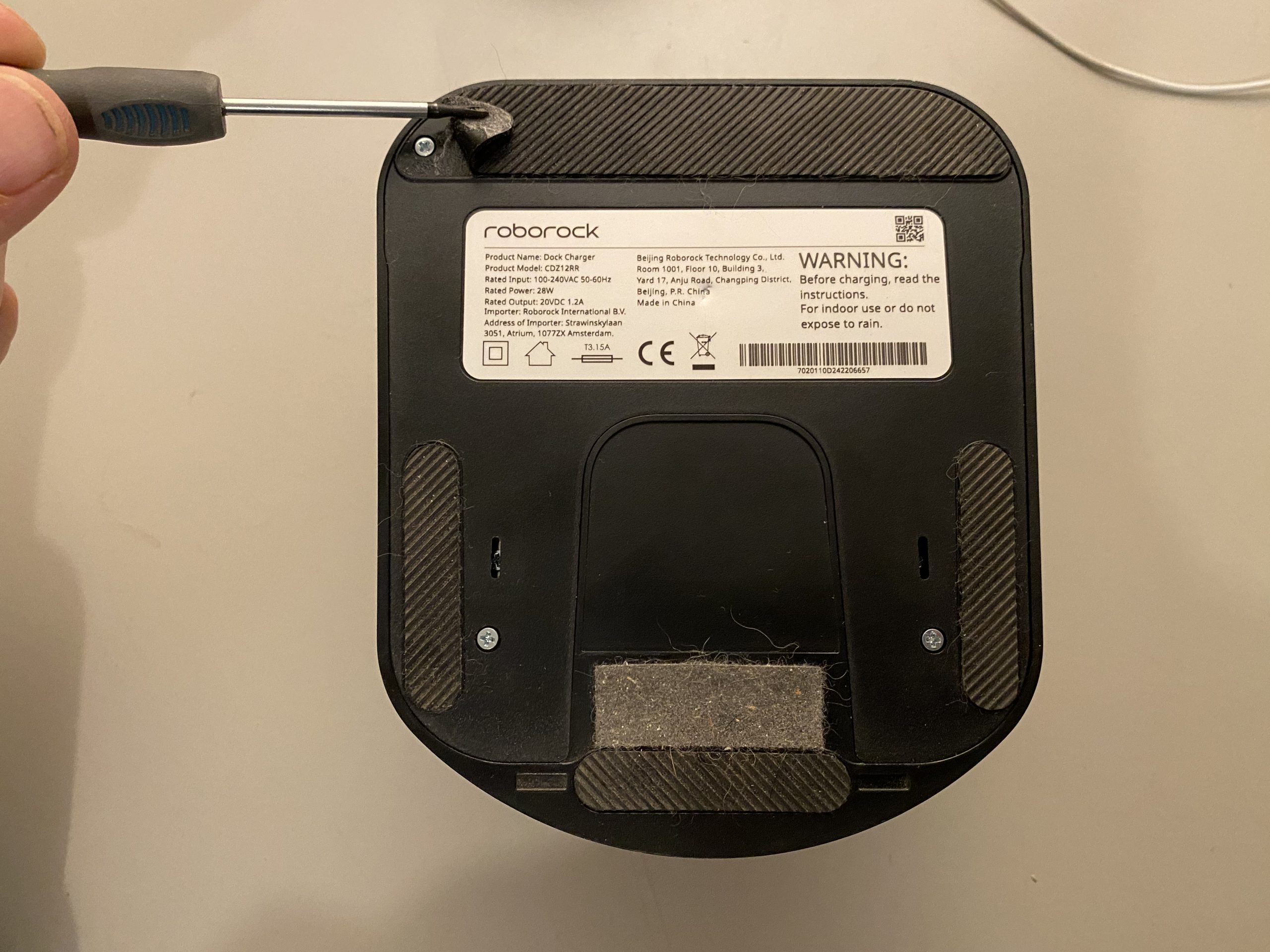
Turn the dock upside down. The bottom cover is held in place by four Phillips screws. Two screws are immediately visible, while the other two are hidden underneath the ends of the large black anti-slip rubber strip at the rear. There is no need to remove the complete strip: carefully lift both corners far enough to reach the screws underneath.
After removing all four screws, the bottom housing can be lifted off.
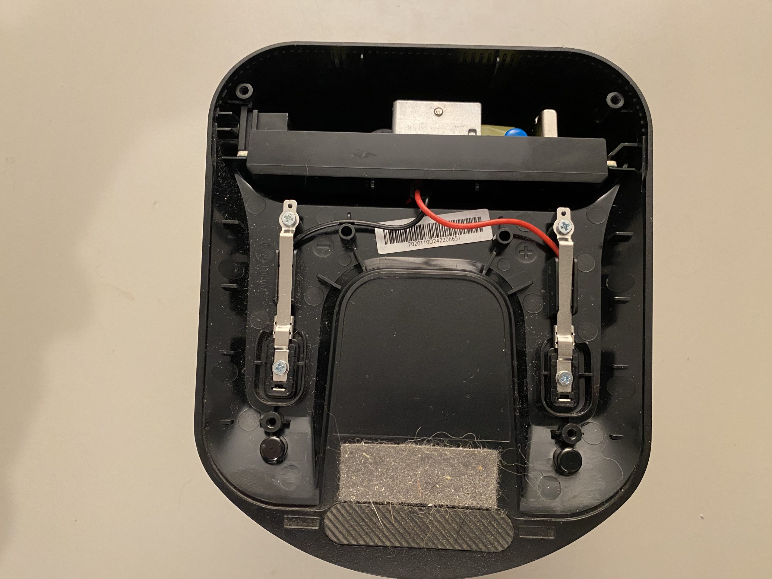
Inside the housing, remove the three screws securing the electronics assembly. The complete electronics section can then be carefully slid out of the housing. Take care with the wires leading to the charging contacts and the small front/IR board; do not pull the assembly out by the wires.
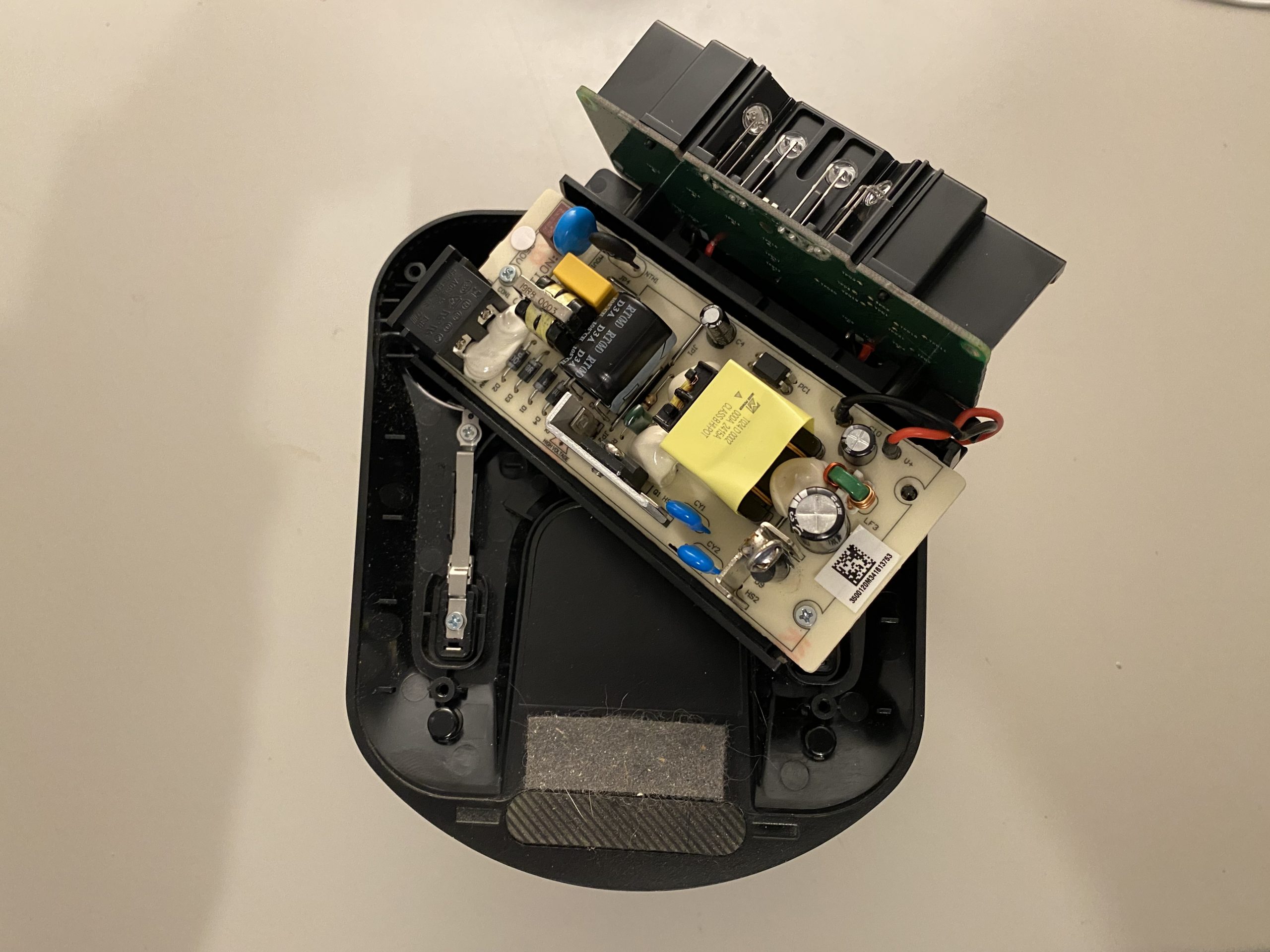
Once the electronics assembly has been removed, the actual power-supply PCB is held to its plastic carrier by two additional screws. Remove these two screws and the component board can be taken out for inspection and measurement.
First: analyzing the power supply
The dock contains a fairly conventional switched-mode power supply. In simplified form, the power path is:
230 V AC → rectifier → primary bulk capacitor → switching transistor/PWM controller → transformer → secondary rectifier → output
The PCB is conveniently divided into clearly marked PRIMARY and SECONDARY sections.
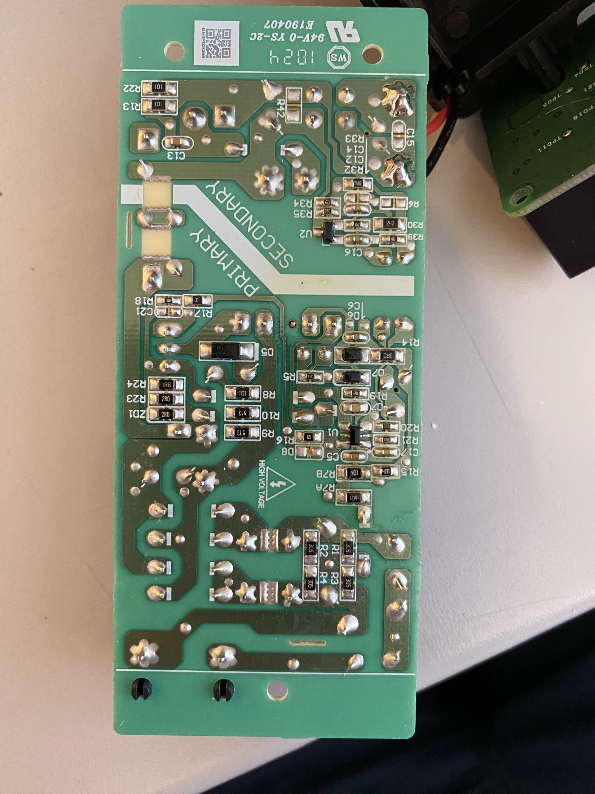
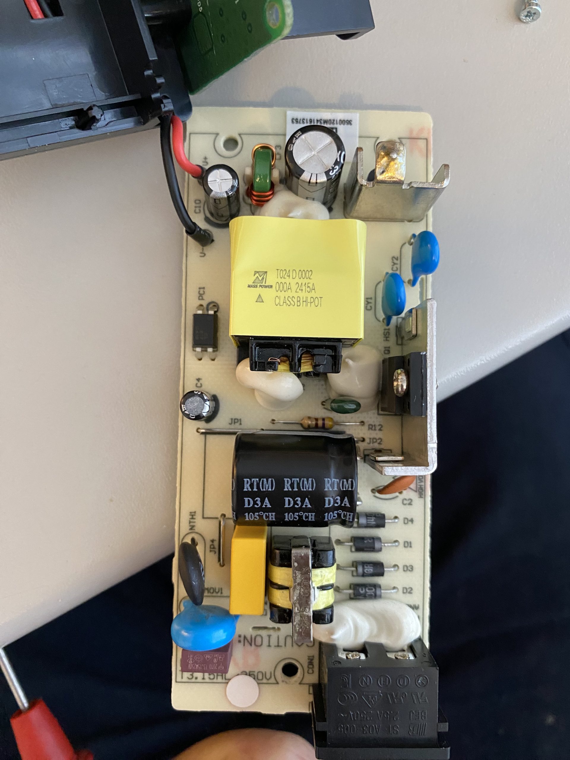
The first step was to check whether the primary side was receiving and rectifying mains voltage correctly. Across the large primary electrolytic capacitor, I measured approximately 313 V DC. That confirmed that the mains input and bridge rectifier were at least working.
That measurement also led to an important reminder about working on switch-mode power supplies: even after the power had been disconnected, the large capacitor still had 313 V on it.
I unfortunately discovered that with my finger as well.
Ouch.
Checking the secondary side
Since the primary side had approximately 313 V DC present but the output remained at 0 V, I continued troubleshooting from the secondary side.
First, I checked for a hard short circuit between the red + and black – output wires. There was no short.
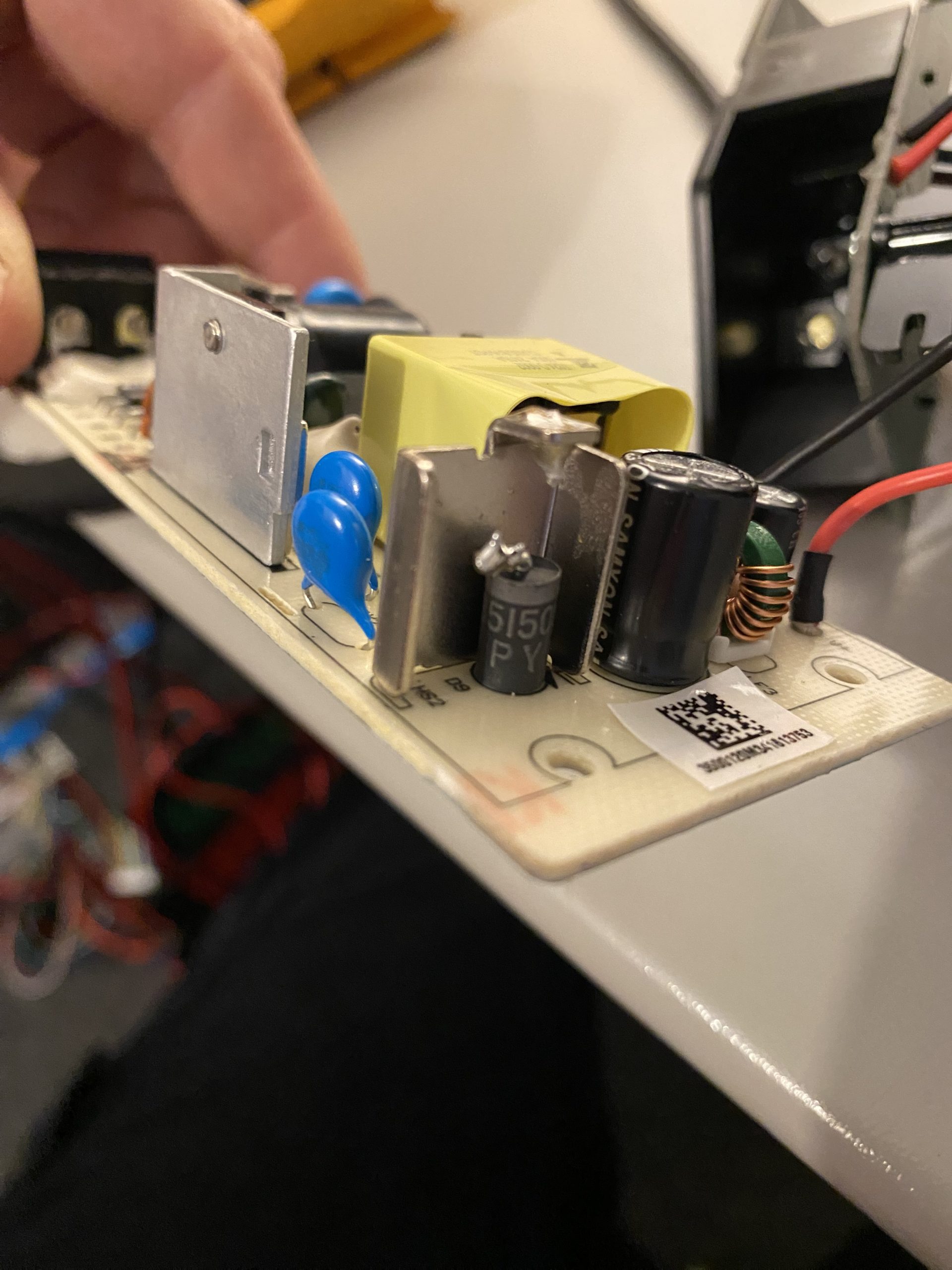
The next suspect was the large secondary rectifier diode. This diode rectifies the high-frequency output from the transformer’s secondary winding.
To get a reliable measurement, I disconnected one side of the diode from the PCB.
The result was very clear:
- diode test in one direction: short circuit;
- diode test in the opposite direction: short circuit as well.
So the diode had failed short.
Temporary test with another diode
Before ordering a replacement, I wanted to make sure there was not another fault elsewhere in the power supply.
In an old parts box I found an RGP10K. This is a 1 A / 800 V fast-recovery diode. It is far too lightly rated to use permanently in the Roborock charger, but it was suitable for a brief no-load test.
After temporarily fitting the RGP10K, the power supply immediately came back to life. The dock’s LED lit up again, and about 4.2 V DC was present across the two metal charging contacts with no robot connected.
That confirmed the diagnosis:
the failed secondary rectifier diode was the cause of the completely dead power supply.
Original diode: SB5150LR
After fully removing the original diode, the marking became readable:
SB5150LR PY
The important part is SB5150. This is a Schottky power rectifier in the 5 A class with a reverse-voltage rating of 150 V. PYis most likely a production or batch code.
For the permanent repair, I therefore chose:
SB5200 (SR5200) – 5 A / 200 V Schottky
This has the same current rating but provides some additional reverse-voltage margin. It is also available in a similar axial package and is well suited for high-frequency switch-mode power supplies.
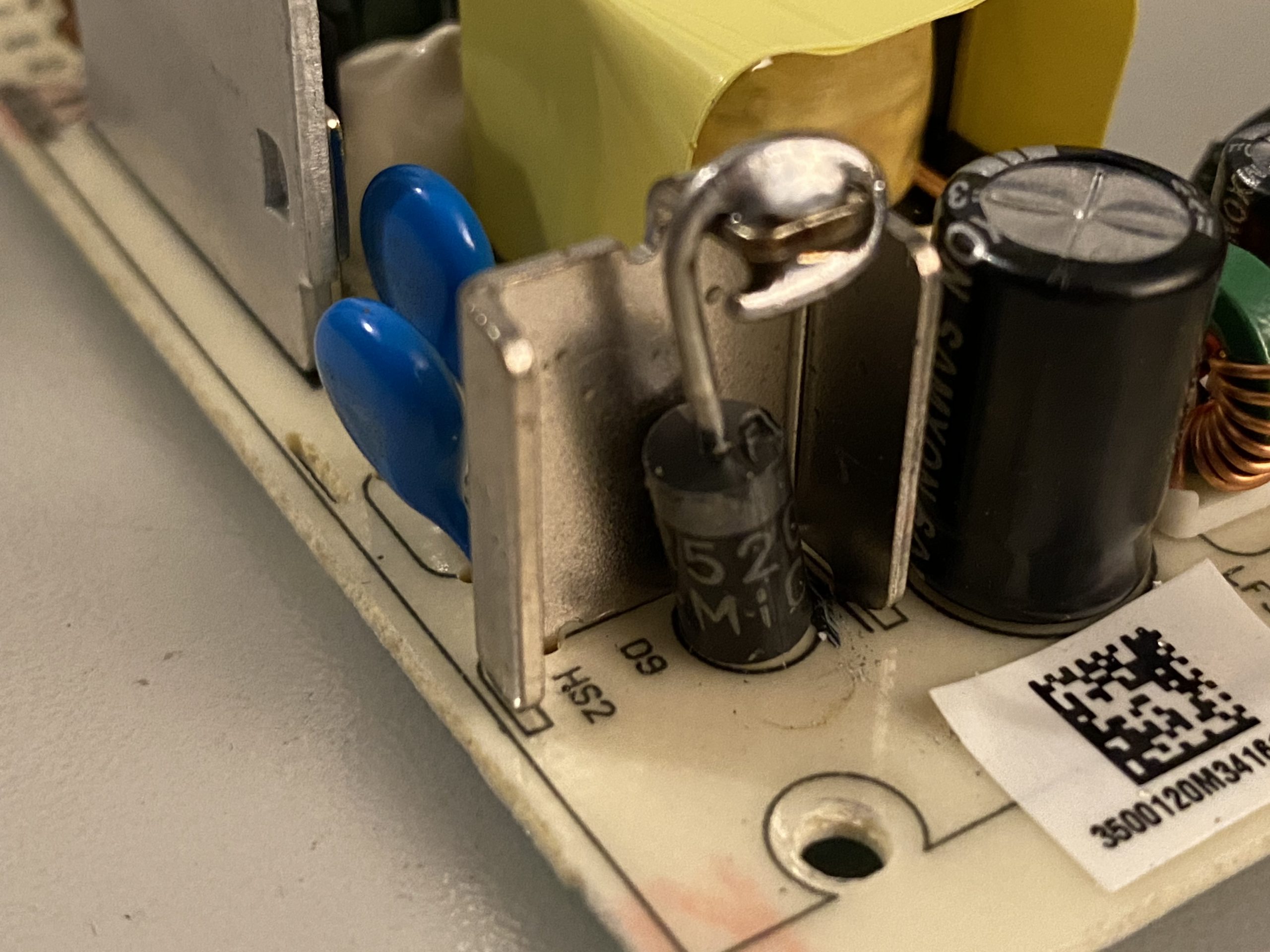
Note: In this article I use both SB5200 and SR5200. These designations are commonly used by different manufacturers for the same type of component: a 5 A / 200 V Schottky rectifier.
In conclusion
In this case, the repair turned out to be surprisingly simple:
one shorted Schottky rectifier diode caused the entire charging dock to produce 0 V. With a temporary replacement diode installed, the power supply immediately started working again.